


In test and measurement scenarios, the APM SP-300 series AC power supplies often need to be integrated with LabVIEW for automated control. This article will use a combination of text and images to explain step-by-step how to configure communication between the power supply and LabVIEW via LAN (Ethernet), helping engineers quickly build a test system.
I. Preparations before communication: Hardware connection and IP Ping test
Before starting the software configuration, you must first ensure that the hardware link is working properly, as this is the foundation for successful subsequent communication.
1. Hardware connection: Connect the Ethernet port of the APM SP-300 series power supply directly to the computer's network port using a network cable, or connect it to a switch on the same local area network.
2. IP connectivity test:
◦ Press the WIN+R key combination, type CMD in the pop-up "Run" window, and click "OK" to open the command prompt.
◦ In the command line, type PING 192.168.10.220 (this is the default IP of the SP-300 power supply; if it has been modified, you need to enter the actual IP), and press Enter.
◦ Judgment criteria: If the message "4 data packets sent, 4 received, 0% lost" appears (as shown in Image 1), it indicates that the computer and power supply IP are connected. If the message "Request timed out" appears, three points need to be checked: whether the network cable is plugged in securely, whether the computer IP and the power supply IP are on the same network segment (e.g., if the power supply IP is 192.168.10.220, the computer IP can be set to 192.168.10.XXX, and the subnet mask should match), and whether the Ethernet settings on the power supply are correct (enter the power supply's "ETH SETTING" interface, confirm that the IP is 192.168.10.220 and the subnet mask matches, as shown in Image 2).
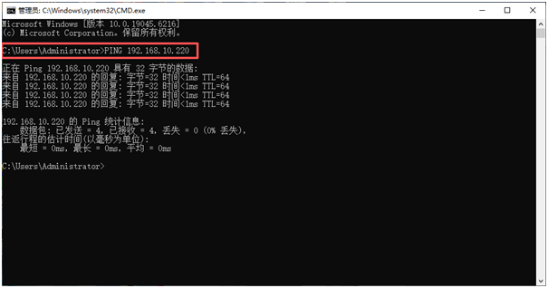
Image 1
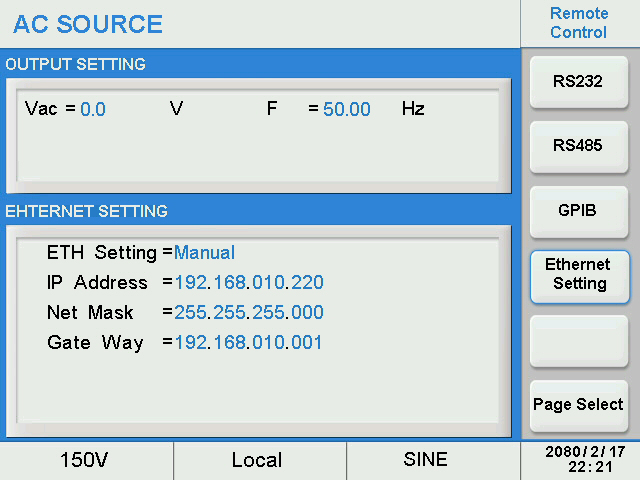
Image 2
II. LabVIEW LAN Driver Configuration: Input Device IP
After the IP connection is established, the LAN driver needs to be loaded in LabVIEW and the power supply IP needs to be specified to establish the association between the software and the hardware.
1. To enable the LabVIEW LAN driver: Launch the LabVIEW software, locate and open "LAN(UDP)_Communication Subvi.vi" (SP-300 series power supply dedicated LAN communication sub-VI, the driver package can be obtained from APM official website) in the project panel.
2. Enter the device IP: In the “DeviceIP” input box on the VI front panel, accurately enter the power supply IP “192.168.10.220” (as shown in Image 3), ensuring there are no spaces or character errors—incorrect IP input is a common cause of communication failure.
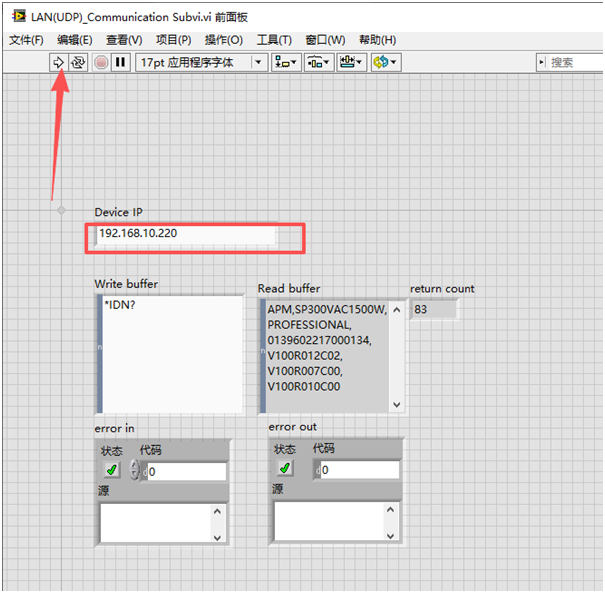
Image 3
III. Communication Verification: Test by sending the *IDN? command.
The standard SCPI command *IDN? (Query Device Identifier) can be used to quickly verify whether the communication between LabVIEW and the power supply is normal.
1. Enter the query command: In the "Write buffer" of the LabVIEW front panel, enter the command *IDN? (Note the English character format, no extra spaces).
2. Run the VI and view the results: Click the "Run" button in the LabVIEW toolbar. If the communication is successful, the "Read buffer" will display the power supply's device information, including the model (e.g., SP300VAC1500W), firmware version (e.g., V100R012C02), serial number, etc. If there is no data in the "Read buffer" or an error message is displayed, you need to check the command format, whether the driver matches, or reconfirm the IP connectivity.
IV. Future Applications: Automation Control Based on LAN Communication
After communication verification is completed, functionality can be expanded based on this framework to achieve automated control of the SP-300 power supply.
• Parameter settings: Enter SCPI commands in “Write buffer”, such as VOLT220 (sets the output voltage to 220V) or FREQ50 (sets the output frequency to 50Hz), to control the power supply output parameters.
• Data Acquisition: Real-time power supply operating data is read from the "Read buffer" using commands such as MEAS:VOLT? (measure output voltage) and MEAS:CURR? (measure output current), and the data is visualized using LabVIEW chart controls.
• Encapsulate the steps of parameter setting, data acquisition, and result judgment into sub-VIs, and write loops or conditional structures to realize unattended testing processes (such as voltage gradient testing and long-term stability monitoring).
By following these three steps, you can quickly complete the LAN configuration between the APM SP-300 series power supply and LabVIEW. The core of the entire process is to ensure IP connectivity and correct command format. Subsequent functionalities can be flexibly expanded according to testing needs, significantly improving testing efficiency.